on
Building a NAS, Part 4: Assembly!
In parts one, two and three, we went from requirements to a honking big Ebay order of various computer parts. Well, they’ve all arrived, and so it’s time to put our machine together.
This post is part of a series:
- Part 1: Requirements
- Part 2: Storage napkin math
- Part 3: Finding and Buying Parts
- Part 4: Assembly (you are here)
This post is mostly going to be a photo album, combined with the surprises and problems we encountered during the build.
Getting to first POST
Before we start building in earnest, it’s a good idea to inspect all the parts you received. Are they the ones you ordered? Is there any damage? For some things like the chassis, dings in the sheet metal are quite common, so you’re really looking for either egregious damage, or damage that prevents correct operation.
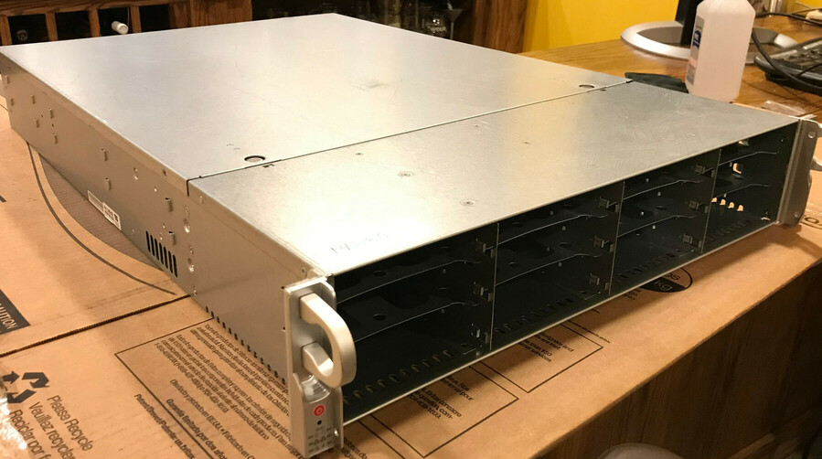
The chassis looks good, and has all the advertised parts (backplane, power supplies of the correct type).
There is one minor piece of damage, the metal near one of the rack ears is slightly bent. It’s extremely minor, doesn’t interfere with chassis function, and five minutes with pliers would see it right if you cared.
Next, we grabbed the motherboard and did a test fit inside the chassis.
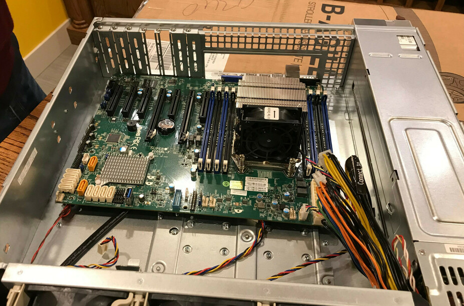
This test fit is to check that the motherboard standoffs are positioned correctly for the form factor we have. In our case, some of the standoffs needed relocating to different positions in order to line up with the drill holes on the motherboard. Don’t forget this step! A grounded metal standoff contacting some random point on the motherboard is a great way to fry the system.
The test fit also illustrated another problem: power cable length.
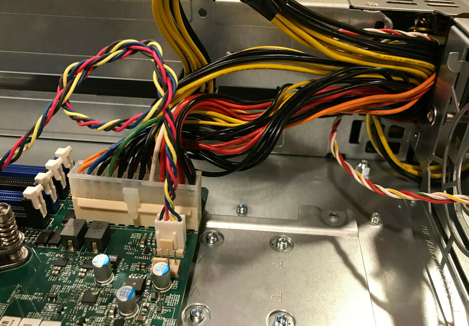
It looks like the original motherboard in this chassis was much larger, and the ATX 24-pin power connector was closer to the PSU distribution box. With our smaller motherboard, the cable only just barely reaches the socket on the motherboard (look at how the orange wires are straining against the connector housing).
You can get the cable plugged in, but doing so puts considerable mechanical strain on the connector and cable. We pressed on with the build to check that everything works, but also ordered an extension cable that we added in when it arrived.
With the motherboard in place, it’s time to install the CPU, so we removed the radiator.
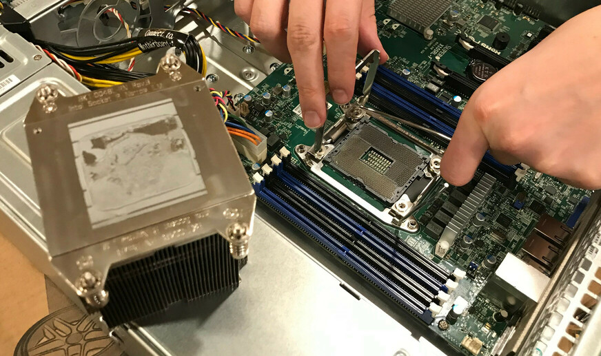
The Ebay vendor from the motherboard shipped a heatsink and fan with it, but not the CPU. They didn’t bother to clean the old thermal pad off the heatsink, but that’s par for the course.
But, having removed the heatsink, something much more serious than leftover thermal paste showed up. It’s a little hard to see in photos, but was plain as day in person.
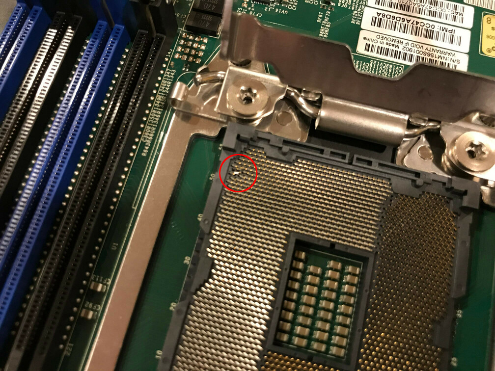
Oh dear. Our CPU socket has some bent pins.
This was a risk I was worried about when ordering a motherboard that comes with a heatsink but no CPU. Vendors typically ship such boards with the heatsink screwed onto the naked socket, acting as a makeshift protector for the fragile pins. However, this isn’t a substitute for the proper OEM socket shield, and in this case, somewhere along the line, the socket took an impact that bent some pins out of alignment.
In my book, this is grounds for an immediate damaged item return. However, the person this NAS was for is braver than I am, and also has steadier hands. Using a fine pair of tweezers, they very, very carefully bent the pins back into the same orientation as the others.
I can’t stress enough that I do not recommend doing this :). These sockets are very fragile, the pins are tiny, their layout causes various optical illusions that make it hard to clearly see the pin(s) you’re working on, and any remaining misalignment could permanently damage the CPU… Which sucks when your CPU costs $235, as this one does!
In this case, the box’s owner decided to risk it, and after some careful bending, the pins were back in alignment. You could still see a slight offset if you knew where to look, but a casual inspection wouldn’t have revealed anything amiss.
With that, we’re now even more anxious to get the machine booted, to see if the repair worked!
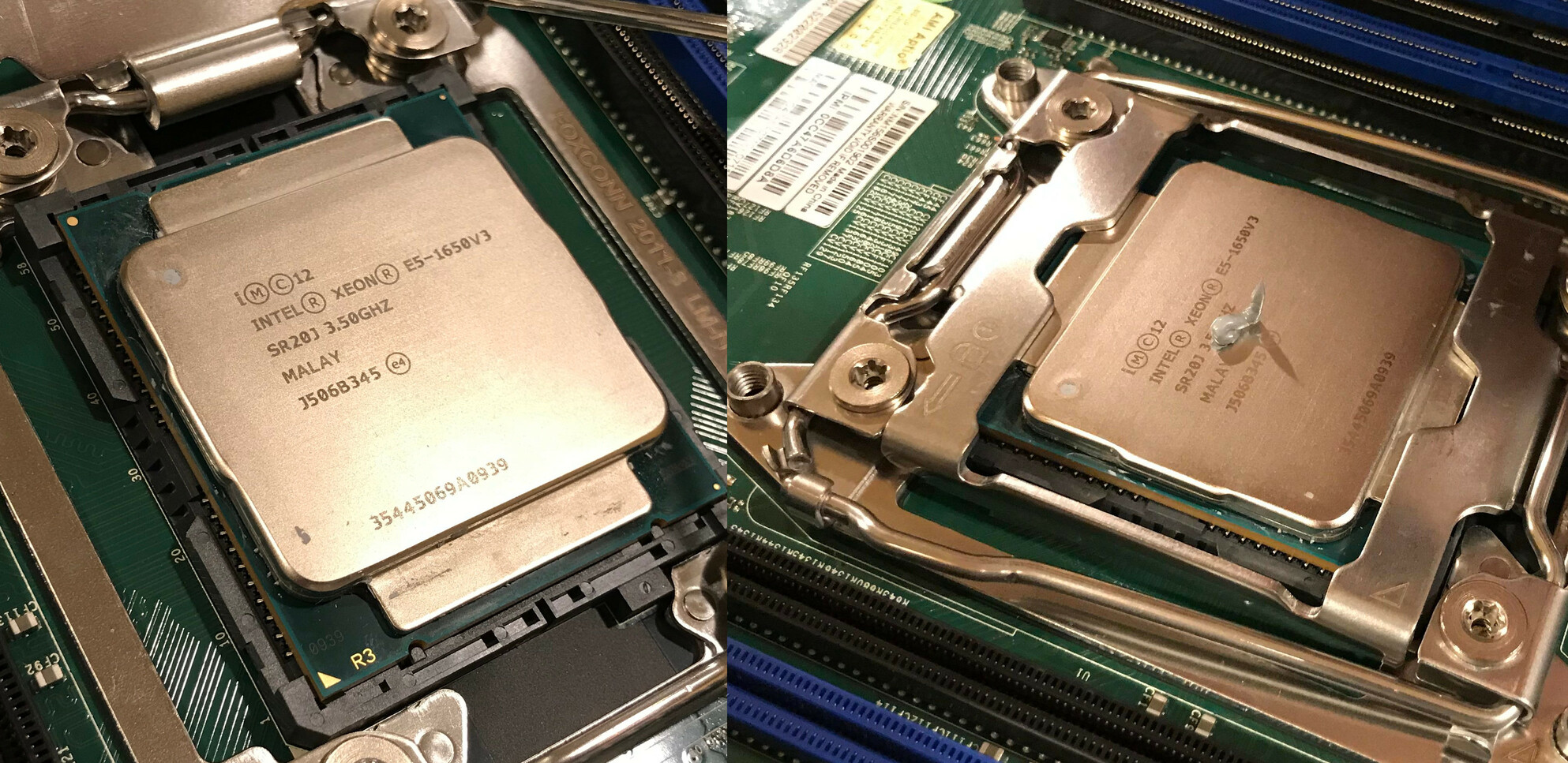
Installing the CPU in these sockets is a simple matter of dropping it in and closing the retention mechanism over it. One rice grain of Noctua NH-T1 thermal paste later, we’re ready to reinstall the heatsink… As soon as we clean off that old thermal paste residue.
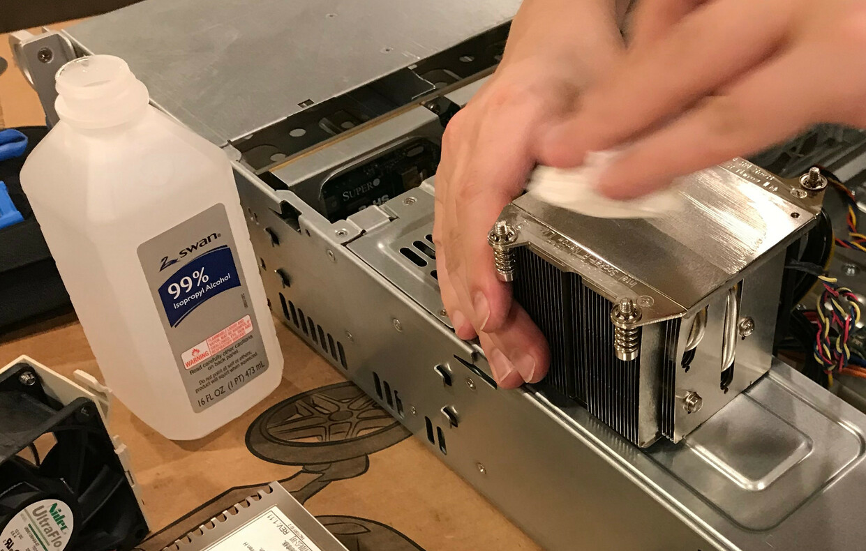
We used isopropyl alcohol on a paper towel to remove the old thermal goop and get the mating surface completely cleaned, and finally a tiny bit more alcohol on a microfiber cloth to remove any paper towel strands that might have stayed behind on the imperfections in the metal.
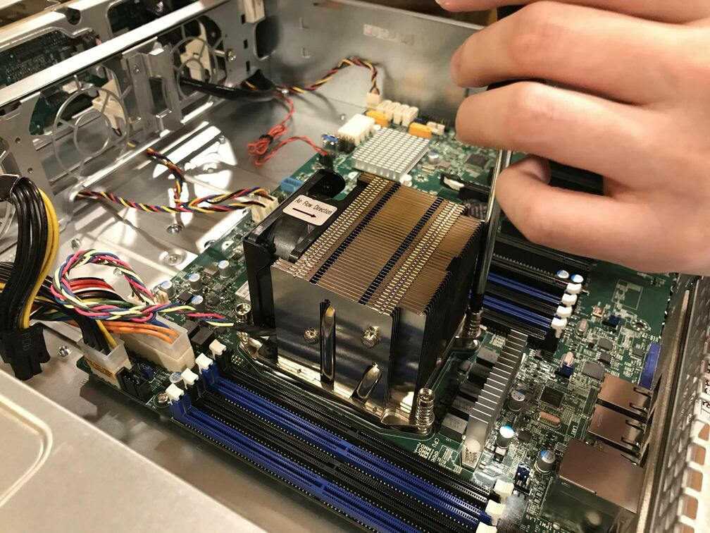
This heatsink attaches to the CPU socket with 4 screws. When installing the heatsink, make sure to tighten down the screws in increments, following a star pattern: loosely tighten one screw, then tighten the one diagonally opposite, then one of the remaining two, then the one diagonally opposite that. Go around multiple times, tightening a little each time, until all four screws are snug.
Following a star pattern applies pressure to the CPU progressively and evenly, which ensures that the thermal paste spreads nice and evenly around the center of the CPU’s surface.
After that, we popped in the sticks of RAM, connected the chassis buttons to the motherboard (there’s a single cable for all buttons and LEDs), hooked up one of the power supplies to the mains, and pushed the switch.
Success! Sort of. The chassis and CPU fans all fired up at full speed and noise, then settled down to a quieter hum once the Management Engine finished booting. But, the display remained blank, no signal.
Troubleshooting first POST
At this stage, we’re worried that the socket repair didn’t work. Or maybe the RAM is giving the machine trouble, or maybe the CPU is a dud?!
Well, the fans are spinning, so the machine’s got as far as the management engine running, at least. And, consulting the manual, a little blinking LED on the motherboard indicates that the BMC1 has booted and is happy.
We connected an ethernet cable to the machine’s management port, and set about trying to log into the management interface to see what it thought. First challenge, with used motherboards: what’s the IP address of the management interface?
Fortunately, the previous owner has left the management chipset configured to use DHCP, so after reading the BMC’s MAC address off a sticker on the motherboard, we found its IP address in the DHCP leases file on the home router.
We logged into the management interface (default credentials,
ADMIN/ADMIN - yes, in all caps), poked around, and found a POST code:
0xDA.
First of all, that’s (somewhat) great news! The fact that there’s a POST code at all means that the CPU is executing instructions, meaning it’s at least partially working.
Looking up that code in the Supermicro manual, we found that 0xDA
means “Boot Option is Failed (StartImage returned error)”. StartImage
is the very last phase of the boot process in UEFI, the point at which
UEFI hands off control to the OS bootloader. This error means “I
couldn’t find a valid OS to boot”.
Fantastic! That means we got all the way through BIOS initialization, and from the machine’s perspective the only problem is that we don’t have any OS. That’s expected, we haven’t plugged in any disks yet, much less installed an OS.
But if things seem to be working from the BMC’s perspective, why are we not getting video output? After checking all the cables and power, we were considering scrounging for a different monitor. But then, staring in confusion at the motherboard, we found this.
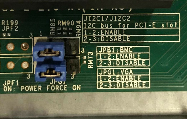
It turns out, on this motherboard you can physically disable the video chipset by flipping a jumper. I have no idea why you’d want to do that, especially since that also disables the remote console in the management interface… But the previous owner of this board had done just that.
Turns out, if you disable video out, you don’t get video out. Go figure! So we flipped the jumper back to the “Enable” position (as pictured above), power-cycled the machine… And we were greeted with the happy Supermicro ASCII art logo!
Going into the BIOS confirmed that our CPU seems fully happy and functional. All cores are there, the management engine is in a good state, all the RAM is detected. We’d want to run some CPU burn-in to make sure we don’t have any more subtle problem from the bent pins, but at first glance, it looks like the repair worked!
Finishing assembly
The rest of assembly was quite boring. Unpack PCIe cards, install PCIe cards, connect any cables that still needed connecting, and, um, that’s about it.
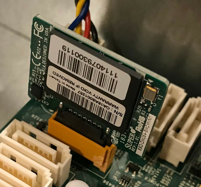
To break up the monotony, here’s a closeup of the SATA DOM2 that will host the machine’s OS…
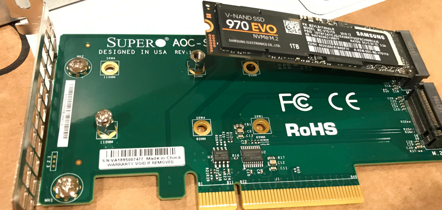
… And a shot of the NVMe addon card, receiving a Samsung 970 EVO SSD…
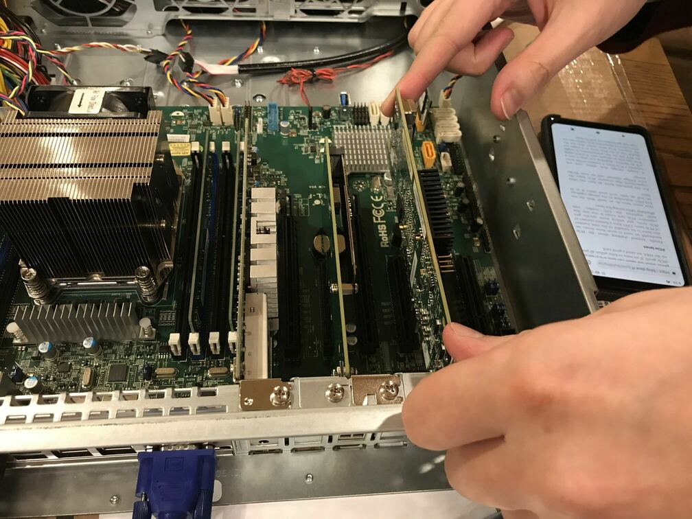
… And a view of the 10G NIC, NVMe expander, and SAS HBA cards, all plugged into the motherboard.
And finally of course, we used zip ties to cable manage things such that the chassis fans have unimpeded airflow through the case.
Installing hard drives
Leaving the best for last, we hooked up the chassis backplane to the motherboard: 2 SAS cables running from the HBA card to 8 of the drive bays, and a SATA-to-SAS reverse breakout cable to light up the last 4 bays.
Then, we unpacked the drives, attached them to the hotswap sleds, booted into a sacrificial Debian install, and started slotting drives in.
After connecting the first drive… Nothing, lsblk reports no new
block device. Oh dear. We connected a second drive… and were greeted
with a slew of SATA command errors in dmesg. Oh dear.
After a bunch of debugging, we figured out that we had two separate issues.
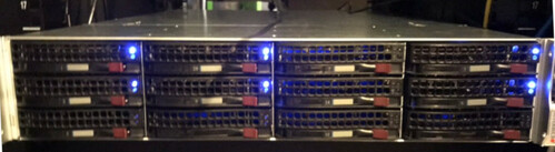
The first was very simple: one of the drives was DOA! When plugged in, Linux would detect it and issue a command to spin it up, but the drive never reported a successful spin-up. This was actually doubly visible via the backplane’s drive LED, which blinks while spinning up the drive and then goes solid once the drive is operational. In this drive’s case, it just blinked for ever.
The second issue stemmed from something I just didn’t anticipate: the machine owner bought SAS drives, not SATA drives. It wasn’t particularly intentional, it just so happened that SAS drives were cheaper on the day they placed the order.
The slew of SATA errors occured when we plugged the drives into the bays hooked up via the SATA-to-SAS reverse breakout cable. It turns out that while a SAS controller can speak to SATA drives, a SATA controller cannot speak to SAS drives. Oops.
Thankfully the remaining 5 non-DOA drives worked fine when connected to the bays managed by our SAS HBA. So, aside from returning the dead drive for a replacement, the only remaining question was: what to do about the four SATA-only bays?
Our options were:
- Return all the SAS drives and exchange them for SATA drives. This is a bit silly, because the SAS drives are nicer in every way.
- Use SAS drives in the 8 SAS-capable bays, and only use SATA drives in the remaining 4. Since the build is starting life with only 6 drives, that’s a workable option, but it feels wrong to leave a weird gotcha lurking in the build to bite us in future.
- Get a second PCIe SAS HBA, and hook the last 4 drive bays into that instead of using a SATA reverse breakout cable.
As you might have guessed, we ended up going with the third option, and bought a second LSI 9207-8i card. That cost another ~$80 for the card and SAS cable, but the owner felt it was worth it to have a completely uniform machine with no weird asymetries.
Fortunately, the Xeon E5 platform and the motherboard we’d picked had just enough PCIe x8 slots to accomodate all 4 of our PCIe cards with no loss of bandwidth to any of them. Unfortunately that leaves only one x4 slot for future additions, but fortunately the owner’s future plans only involve consuming one more low-ish bandwidth slot. Phew.
Conclusion
The build is done! And it works!
We definitely had a scare with the CPU socket damage, but so far (fingers crossed) it looks like the field repair worked perfectly. We also established that the previous owner of the motherboard was an eccentric who disabled VGA output and blocked execution of PCIe option ROMs (that’s a story I skipped – we had a brief moment of terror when none of the PCIe cards seemed to be detected).
Aside from those minor adventures, the only real failure of the build was a brand new hard drive that was dead on arrival, and my failure to realize that buying SAS drives (the owner consulted with me on what drives to get) wouldn’t play well with our planned storage topology.
All in all, I’d call that a reasonably successful build, although slightly more eventful than I’d have ideally liked! The machine is now running Proxmox, and happily storing bits on ZFS in its new home.
Thanks for following along! Questions, thoughts? Hit me up on Twitter. I might also do a final followup to describe my own personal NAS build, which follows the same general lines but makes different cost/performance tradeoffs. Stay tuned for that, maybe!